
Reliable Test Equipment Manufacturer
Reliable Test Equipment Manufacturer
|
Battery forced internal short circuit tester
Telephone:+86 13794880254
Mail:carleen@sailham.com
|
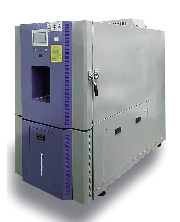
Battery Forced Internal Short Circuit Tester
ZH-SC-60C
1. Introduction.
The battery forced internal short circuit tester simulates the battery to conduct forced internal Short-circuit test under certain ambient temperature conditions. The test box is made of stainless steel, has good temperature uniformity, and has the air exhaust function (that is, exhaust the test exhaust gas after the test is completed). The control system of the testing machine adopts a PLC touch screen menu operation, with a data collection frequency of up to 100 times/second. At the same time, the testing pressure, pressure holding time, measured pressure, battery voltage, battery temperature, pressure drop speed, etc. are set through PLC programming.
2. Conforms to the standard
JISC8714:2007 Safety Testing of Portable Lithium Ion Secondary Batteries and Batteries Used in Portable Electronic Applications
IEC 62133 Safety Standard for Portable Rechargeable Secondary Batteries and Batteries Containing Alkaline or Other Non acidic Electrolytes
3. Test purpose.
During the production process of the battery, due to careless process control, extremely small metal particles were mixed inside the lithium-ion battery. During battery use, due to temperature changes or various impacts, the metal particles pierced the separator between the positive and negative electrodes, causing a short circuit inside the battery, causing a large amount of heat and causing the battery to catch fire. Due to the accidental inclusion of metal particles during the production process, it is difficult to completely prevent such incidents from occurring. Therefore, through the "forced internal short circuit test" to simulate the situation where metal particles penetrate the separator and cause internal short circuits, if lithium-ion batteries can ensure that there is no risk of fire or explosion during the test process, it can effectively ensure that even if metal particles are mixed inside the battery during the production process, they cannot penetrate the separator between the positive and negative poles; Or even if the diaphragm is punctured and an internal short circuit is caused, there will still be no danger of fire or explosion that endangers personal safety.
4. Single battery forced internal short circuit test conditions.
The number of test samples for the "single battery forced internal short circuit test" is 10, with 5 samples for each upper and lower limit test conditions.
The test steps are divided into:
1) Charging steps for the test;
2) Disassemble the battery and place small nickel sheets;
3) Wrap the battery back and bring it to the test temperature;
4) Pressure application steps.
Steps in detail:
1) Charging steps for the test
The "Single Battery Forced Internal Short Circuit Test" is a test conducted on a fully charged single battery. The charging conditions are: after stabilizing at the upper and lower test temperatures for 1-4 hours, using the upper and maximum charging voltage and current, the current value when charging to the constant voltage charging control becomes 0.05ItA. The upper and lower test temperatures indicate the highest and lowest temperature on the surface of the battery cell when the battery can use the upper and lower charging voltage and maximum charging current. The reason for charging under the upper and lower test temperature conditions is determined based on the material characteristics of lithium batteries. The upper and lower test temperatures proposed by JIS C 8714 are 45 ℃ and 10 ℃, respectively, and the upper charging voltage is 4.25V. This condition is based on the characteristics of commonly used lithium-ion batteries (lithium cobalt oxide negative electrode carbon positive electrode) materials on the market, and cannot represent all lithium batteries. In JIS C 8714, it is proposed that if new upper and lower test temperatures and upper charging voltage are required, certain tests need to be conducted and additional data basis needs to be supplemented. The investigation content for determining the new upper limit charging voltage includes: the structural stability of the positive electrode material, the lithium absorption of the negative electrode material, and the structural stability of the electrolyte; The inspection content when determining the new upper and lower limit test temperatures includes: the structural stability of the positive electrode material, the structural stability of the electrolyte, and other material characteristics. It is necessary to ensure the safety of the charged battery at the new upper limit test temperature, and add 5 ℃ to the new upper limit test temperature, which is applicable to the charging conditions of Article 5.1 of JIS C 8714, and comply with the test requirements of Articles 5.2 to 5.5; Based on the lithium ion absorption of the negative electrode material and the lithium ion mobility of the electrolyte (corresponding to temperature), it is necessary to ensure the safety of the charged battery at the new lower limit test temperature, and add -5 ℃ to the new lower limit test temperature to meet the charging conditions of 5.1, and meet the test requirements of 5.2 to 5.5.
5. Specification.
Temperature control system:
5.1. Temperature range: -10 ℃~100 ℃
5.2. Analytical accuracy: 0.1℃
5.3. Temperature fluctuation:±0.5℃
5.4. Temperature uniformity: ±2.0℃
5.5. Temperature rising rate: 1-3 ℃/min (non-linear no-load)
5.6. Temperature cooling rate: 0.7-1 ℃/min (non-linear no-load)
5.7. Inner test space: W 500 x D 500 x H 600mm;
5.8. Inner material: 304 stainless steel plate with bottom reinforcement;
5.9. External material: Cold rolled sheet with paint treatment;
5.10. Temperature control system: Programmable 7’’ touch screen control
5.11. Safety protection device: Fuseless switch, compressor high voltage, overheating, overcurrent protection, overtemperature protection, fan overload protection, fuses, etc
Pressure control system:
5.12. Test load: Maximum 100Kg (commonly 80kg)
5.13. Load resolution: 1/10000
5.14. Unit:Kg, lb, N
5.15. Load accuracy: FS≤±0.5%
5.16. Displacement resolution: 1/1000
5.17. Displacement accuracy: ±0.05mm
5.18. Speed range: 0.01-20mm/s, adjustable (commonly used test speed 0.1mm/s)
5.19. Effective stroke: 100mm
5.20. Test plane: 200x200mm (can be customizable)
5.21. Voltage collection range: 0~20V
5.22. Voltage resolution: 0.1mV
5.23. Voltage acquisition frequency: 100 times/s
5.24. Pressing head size: 5x5x2mm / 10x10x2mm / 10x10x15mm
5.25. Pressing head material: One piece of nitrile rubber and one piece of acrylic each
5.26. Control system: PLC control
Phone
+86 13794880254
carleen@sailham.com
Applets

Mobile station
Mobile station QR code


